
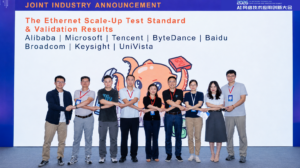
At the recently held 2026 AI Networking Technology & Innovation Conference, the SONiC community Scale-Up Working Group announced the latest LLR/CBFC testing progress of the Ethernet Scale-Up Verification Test Standard (SONiC Scale-Up Test Standard)[^3].
-
What Is Ethernet Scale-Up?
Let’s start with the most fundamental question: training a large AI model requires hundreds or thousands of accelerator cards working together — how do these cards interconnect?
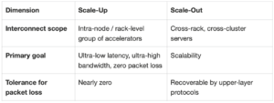
The industry classifies interconnection into two categories. Scale-Out (horizontal scaling) is “building more buildings”: connecting more servers via a network, with scale growing indefinitely. Scale-Up (vertical scaling) is “making one building bigger”: connecting a group of accelerator cards with ultra-high bandwidth, ultra-low latency links into a single “big machine,” where cards exchange data as if they were on the same motherboard.
The differences can be summarized in one table:
Traditionally, Scale-Up has relied on proprietary interconnects. UEC (Ultra Ethernet Consortium) is driving the use of standard Ethernet for this layer of interconnection, on the premise that Ethernet must achieve hardware-level zero packet loss[^2].
Note that Scale-Up and Scale-Out are two networks with different goals. Do not directly apply Scale-Out experience (e.g., “if packets are lost, let the transport layer retransmit”) to Scale-Up — in the next two sections, you will see that Scale-Up pushes both retransmission and flow control down to the link layer.
Key takeaway: Scale-Up is the network that connects a group of accelerator cards into “one big machine” — it is most sensitive to packet loss and latency.
-
What Is LLR?
A bit error occurs on the link, corrupting a frame — what happens? This is the first question Ethernet must answer for Scale-Up.
LLR (Link Level Retry) is a mechanism defined by UEC: the hardware at both ends of a link enumerates each frame and acknowledges them one by one. When a corrupted frame is detected, it is immediately retransmitted on the same link, entirely transparent to the host[^1].
Think of it like a package station receiving deliveries: if a parcel is damaged, the station rejects it on the spot and the courier immediately delivers a replacement. The entire process requires no phone call to the e-commerce platform to resend the order — that would be transport-layer retransmission, a much longer path.
LLR behavior can be summarized in three paths[^1]:
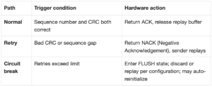
ACK/NACK and other control signals are carried via out-of-band signaling units, referred to in the standard as CtlOS (Control Ordered Set)[^1].
Note that LLR addresses “packet loss caused by bit errors,” not “packet loss caused by congestion.” Buffer overflow prevention requires the flow control mechanism described in the next section.
Key takeaway: LLR repairs bit-error-induced packet loss locally at the link layer, transparent to the host.
-
What Is CBFC?
The receiver’s buffer is nearly full — if more data arrives, packets will be dropped. What to do?
CBFC (Credit-Based Flow Control) works on the principle of “only proceed if there is room.” The receiver issues credits to the sender based on its remaining buffer space; the sender can only transmit data while holding credits; once data is processed and buffer is freed, credits are returned to the sender[^1].
Think of it like a restaurant reservation system: tickets are issued based on available tables, and customers can only enter with a ticket. The restaurant never gets overcrowded because the act of “entering” is controlled before it happens.
Credit transactions are tracked end-to-end in hardware counters. The core counters defined by the standard are[^1]:
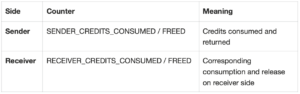
These readings must match theoretical formulas — this is the foundation for pass/fail determination later.
Do not confuse CBFC with PFC (Priority-based Flow Control). PFC works by “shouting stop when nearly full,” triggering backpressure based on buffer watermarks. CBFC works by “only proceed if there is room,” constraining the send action from the very beginning. The two prevent packet loss at different points in time.
Key takeaway: CBFC turns “zero packet loss” from an after-the-fact recovery into a constraint that holds before transmission even begins.
-
Who Defined This Standard?
You might ask: UEC, ESUN, and SONiC are all working on Ethernet Scale-Up — what is the relationship between them?
The three build upon each other in layers[^2]. Using a building analogy: UEC writes the “building code” — publishing the LLR and CBFC protocol specifications; ESUN (Ethernet for Scale-Up Networking) persuades the industry to build according to this code — driving adoption of Ethernet solutions to replace proprietary interconnects; the SONiC community Scale-Up Working Group provides the construction blueprints and acceptance checklist — delivering multi-vendor interoperable cluster reference architectures, and the core of this article: the test standard.
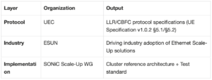
Basic information about the test standard: SONiC Scale-Up Test Standard, current version Draft v0.4 (June 2, 2026), developed by the Test Subgroup under the Working Group. The subgroup was initiated by Alibaba Cloud, in collaboration with Baidu, Broadcom, ByteDance, Keysight, Microsoft, Tencent, and Univista. The document is publicly available as a PR (Pull Request) in the SONiC community repository[1].
Note the “Draft v0.4” status: it is still a draft, and criteria and test cases may be revised through community review. Do not cite draft provisions as finalized standards.
Key takeaway: The test standard is a multi-vendor “acceptance checklist” co-developed by the SONiC community, built upon the UEC protocol and ESUN industry consensus.
-
Why Doesn’t a Protocol Specification Equal Deployability?
UEC has already specified LLR/CBFC clearly — why is a test standard still needed?
Because protocol specifications primarily describe the normal path, while production environments test boundary conditions[^3]: How should a frame with a Poison CRC be handled under different forwarding modes? If a credit signal is lost, how long does recovery take, and will the buffer overflow? Under 3:1 Incast (many-to-one convergence) congestion, what scheduling qualifies as fair?
A specification is like a driver’s license written exam syllabus; the test standard is the road test scoring sheet. The Test Subgroup reverse-engineered from the protocol specification to define 22 standard test cases: 10 for LLR, 12 for CBFC, covering five dimensions[1][3]:
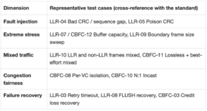
Take Poison CRC as an example: according to the LLR-05 criteria, the receiver must identify frames “already marked as corrupted by upstream” but must not trigger retransmission[^1]. This kind of detail is mentioned in passing in the specification text; the test case turns it into a mandatory check item.
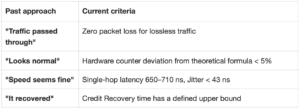
Do not assume that “traffic passed through” equals “specification-compliant.” These 22 test cases deliberately construct paths you would never hit in normal operation — for example, intentionally injecting a bad CRC frame, then verifying that the NACK counter increments by exactly one.
Key takeaway: The test standard translates each protocol requirement into an executable, auditable test case.
-
How Is Pass/Fail Determined?
After running the test cases, how do you determine “pass”? The common past practice was “if it runs, it passes.” This standard provides quantitative criteria[1][3]:
For the counter criterion as an example, deviation is calculated as:
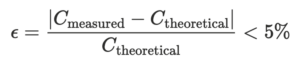
Substituting an illustrative number: if a test case theoretically should consume 10,000 credits, then the measured reading must fall between 9,500 and 10,500 to pass (illustrative; theoretical values for each test case are given by formulas in the standard).
The latency criterion can similarly be calculated: the qualifying window width is only:

Combined with the constraint that jitter must not exceed 43 ns, device behavior must be highly deterministic — “looks normal” would not pass.
Note that these numbers are tightly bound to test conditions: the criteria and measured results published here are based on a 4×400GE test environment[^3]. Do not use these latency ranges for cross-comparison with devices at different speeds or different topologies.
-
How Large Must the Buffer Be? — A Quantity You Can Calculate Yourself
LLR requires retransmission, which means frames that have been sent but not yet acknowledged must be stored in a replay buffer. How much storage is enough?
The answer is determined by one physical quantity: bandwidth × round-trip time (RTT). Before the ACK returns, frames cannot be released; at line rate, all data sent within one RTT is in an “unacknowledged” state. Think of it as a package station’s temporary shelf: it must hold at least all “sent but not yet signed for” parcels.
Standard test cases LLR-07 and CBFC-12 stress-test exactly this: on the test equipment, they simulate a control signaling delay equivalent to a 500 m link RTT, then send traffic at 100% line rate, requiring zero packet loss with the receiver maintaining line-rate throughput[^1].
You can estimate the lower bound behind this test case yourself (illustrative calculation below). Fiber propagation delay is approximately 5 ns/m (public knowledge), so the round-trip time for a 500 m link is:

At a single-port 400 Gbps line rate, the in-flight data volume is:

This means the replay buffer must be at least on the order of 250 KB to achieve zero packet loss in this scenario.
Note that this is only an illustrative physical lower bound: inter-frame overhead and signaling processing delays are not included, so actual requirements are larger. Do not treat this as the actual specification of any device — precisely because this parameter is important, the standard lists LLR_REPLAY_BUFFER_SIZE as a SAI attribute to be defined (see Section 9).
Key takeaway: Buffer ≥ bandwidth × RTT is the physical lower bound for zero-loss retransmission; the standard directly verifies it with a 500 m RTT stress test case.
-
How Is Interoperability Verified?
If a single device passes all test cases, does that guarantee two vendors’ devices will work together without issues? Not necessarily. Protocol stacks from different implementations often reveal behavioral differences only during interoperability testing.
The standard defines a Pairwise interoperability matrix covering four scenarios[1][3]:
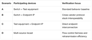
Think of it like an orchestra: each musician first passes an individual exam (Scenario A, against test equipment as the “standard tuning fork”), then plays duets (Scenarios B, C), and finally performs a full ensemble rehearsal (Scenario D).
Note that the four scenarios have non-overlapping verification focuses — missing any one creates a blind spot. Do not use Scenario A pass results to endorse Scenario B — passing against test equipment does not guarantee passing against another vendor’s protocol stack.
Key takeaway: Interoperability quality is determined by running the same test cases across four combinations, not by individual vendor self-declarations.
-
What Else Did Testing Reveal?
Running the standard produced more than just pass/fail results — there was an unexpected output: insufficient interfaces.
Switch silicon capabilities must be exposed through SAI, the vendor-neutral interface (introduced in Section 4). During testing, 17 LLR/CBFC-related SAI attributes and counters were found to be missing or not covered in the current interface proposals[1][3], for example:
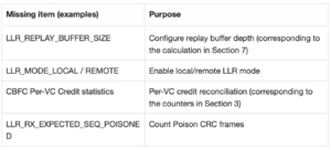
Think of it as a home inspection: during acceptance, you discover the blueprints didn’t indicate where to place the water meter — the blueprints need to be updated before the plumber can install it. These 17 items have been reported back to the silicon vendor to be addressed in the next SDK release[1][3].
Note that “missing” means the interface layer has not yet defined or exposed the capability — it does not mean the silicon hardware lacks it; whether it is supported requires vendor-by-vendor confirmation[^1].
Key takeaway: The test standard exposed interface gaps in reverse, driving SAI interface completeness alongside testing requirements.
Exercise: Check in the switch SDK you use — which LLR/CBFC counters can sai_get_port_stats currently read?
-
How Far Has Verification Progressed?
Is this standard just a paper document, or has it actually been validated? Two sets of measured results were announced at the conference[^3].
The first set was completed on Alibaba’s Ethernet Scale-Up switches — the first devices to complete full-scale verification against this standard. The test environment was 4×400GE, using Keysight INPT 800GE test equipment:
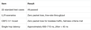
The second set is verification of Univista’s endpoint IP: all LLR test cases passed; most CBFC test cases passed, with 3 remaining incomplete — IPv6-related test cases awaiting version iteration, and N:1 Incast test cases awaiting multi-party joint testing. Core interoperability capabilities have been verified[^3].
Two notes. First, “zero packet loss” is a measured conclusion for lossless traffic class under the test environment described above — do not assume it as a guarantee for production networks of arbitrary scale. Second, the endpoint side still has 3 test cases pending; interoperability verification is in progress, not complete.
Key takeaway: All 22 test cases passed on the switch side; core endpoint interoperability has been verified; the remaining 3 test cases await multi-party joint testing.
-
What’s Next for the Standard?
What comes after v0.4? According to the Working Group’s published roadmap, the standard will evolve from v0.4 to v1.0, incorporating new scenarios[^3]:
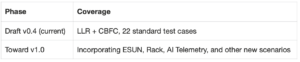
If you want to follow along or participate, the entry point is the standard PR in the SONiC community repository[^1]: the test case matrix, criteria, and missing interface list are all in the document, and review comments are discussed directly under the PR.
Note that the evolution scope comes from the current draft and published materials; the final outcome is subject to community review. Do not treat planned scenarios as capabilities already present in v0.4.
References
[1] SONiC Scale-Up Test Standard (Draft v0.4), SONiC Scale-Up WG Test Subgroup (Alibaba, Broadcom, ByteDance, Keysight, Univista), 2026-06-02, https://github.com/sonic-net/SONiC/pull/2389
[2] Ethernet Scale-Up AI Cluster Architecture, SONiC Community, https://github.com/sonic-net/SONiC/blob/master/doc/scale_up/Ethernet_Scale_Up_AI_Cluster_Architecture.md
[3] “Ethernet Scale-Up Verification Standardization” Joint Release Materials, Alibaba Cloud with Broadcom, Keysight Technologies, Univista, ByteDance, Tencent and Baidu, 2026 AI Networking Technology & Innovation Conference, August 2026.